


 1013 / 1445

HELMETS
HELMET
ACC.
EYEWEAR
APPAREL
PROTECTIVE
BAGS/ SURVIVAL
VIDEOS
SNOWMOBILE
ACC.
SLEDS/
TRAILERS
ELECTRICAL
EXHAUST
ENGINE
STEERING/
CONTROLS
AIR/ FUEL
WINDSHIELDS
BODY
TUNNEL/ RAIL
ACC.
TRACKS/ STUDS/
SPROCKETS
REAR
SUSPENSION
SHOCKS
FRONT
SUSPENSION
SKIS/ RUNNERS
BRAKES
CHAIN/
SPROCKETS
BELTS
CLUTCHING
CHEMICALS
TOOLS/
FASTENERS
PROMOTIONAL
REFERENCE
INDEX
1013
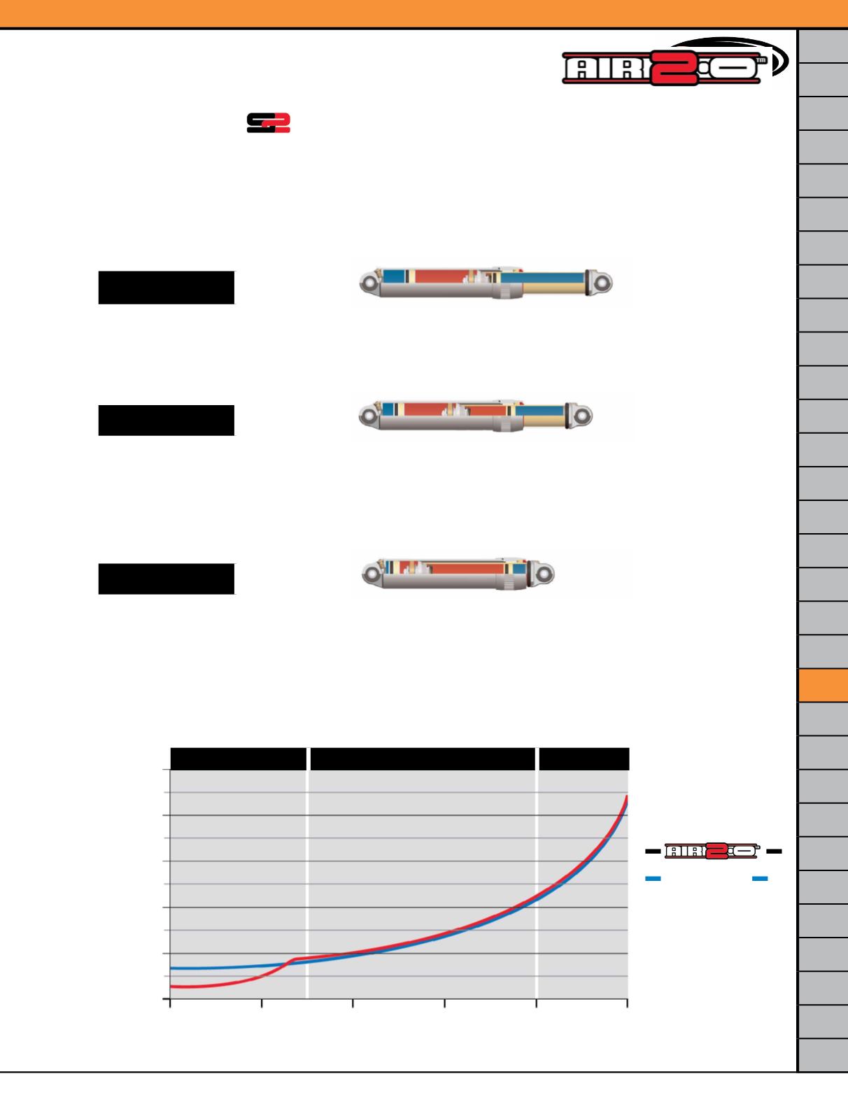
Integrated Dual Rate Technology
The gas spring chamber located within the larger 47mm aluminum cylinder can be set in a range of approximately 50-100
psi to allow for an initial lower “spring” rate. This first stage of “spring” rate manages pressures within 1.0” to 1.5” of shock
stroke for “plush” ride handling characteristics along with adjustments to suspension sag.
As suspension travel and shock stroke increase, the gas pressure within the 47mm aluminum cylinder increase to a level
equal to the gas pressure in the 37mm chrome rod cylinder. At this point the 37mm IFP begins to move which provides a
second gas “spring” rate. Gas spring pressures within the chrome rod cylinder can be set in a range of approximately 120-
220 psi to allow for a stiffer “spring” rate that manages ride quality within the 1.5” to 4.0” of shock stroke.
During the last 1.0” of shock stroke, gas pressures within the 37mm chrome rod cylinder significantly ramp up and act as
an anti-bottoming mechanism. The peak in gas pressure acts very similar in purpose to a mechanical compression bumper
that reduces harsh feedback to the rider.
0
1
2
3
4
5
Stroke (inches)
Spring Rate (lbs.)
2000.0
1600.0
1200.0
800.0
400.0
0.0
Stage 1
Stage 2
Stage 3
▲
▲
▲
Stage 1
_HOW_IT_WORKS!
■
Oil
■
Nitrogen
▲
Stage 2
■
Oil
■
Nitrogen
▲
Stage 3
■
Oil
■
Nitrogen
▲
—
—
—
Competitor
—
SHOCKS